igure 1. Memory module plugging sequence
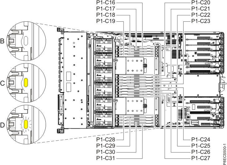
Memory module plugging sequence
  • The 8247-42L, 8286-41A, or 8286-42A system can support short memory modules with a filler to latch into the chassis, along with tall memory modules of 128 GB.
  • The 8286-41A system supports a minimum of one memory module and provides a minimum of 16 GB memory.
  • The 8286-42A or 8247-42L system supports a minimum of two memory modules and provides a minimum of 32 GB memory.
  • A memory module pair must be identical and can be different from the other pairs of memory modules.
  • The 8247-42L, 8286-41A, or 8286-42A system supports various feature codes such as FC EM8B, FC EM8C, FC EM8D, and FC EM8E that have different memory capacities. Ensure that the same feature code are installed in pairs.
    Note: To determine if your memory modules have the same feature code, compare the part numbers of the memory modules installed in the system to the memory modules being installed. If you need additional help, contact your next level of support.
Table 1. Memory module plugging sequence for the 8247-42L, 8286-41A, or 8286-42A system
Number of system processors Plugging sequence
One system processor module (8286-41A, 8286-42A, or 8247-42L)
  1. Install the first memory module at location C16.
  2. Install the second memory module at location C18.
    Note: First and second memory module must be identical.
  3. Install the third identical memory module pair at location C21 and C23.
  4. Install the fourth identical memory module pair at location C17 and C19.
  5. Install the fifth identical memory module pair at location C20 and C22.
Two system processor modules (8286-42A or 8247-42L)
  1. Install the first identical memory module pair at location C16 and C18.
  2. Install the second identical memory module pair at location C24 and C26.
  3. Install the third identical memory module pair at location C21 and C23.
  4. Install the fourth identical memory module pair at location C29 and C31.
  5. Install the fifth identical memory module pair at location C17 and C19.
  6. Install the sixth identical memory module pair at location C25 and C27.
  7. Install the seventh identical memory module pair at location C20 and C22.
  8. Install the eighth identical memory module pair at location C28 and C30.


http://www.ibm.com/support/knowledgecenter/en/8247-42L/p8had/p8had_sascabling5887.htm?cp=8286-42A


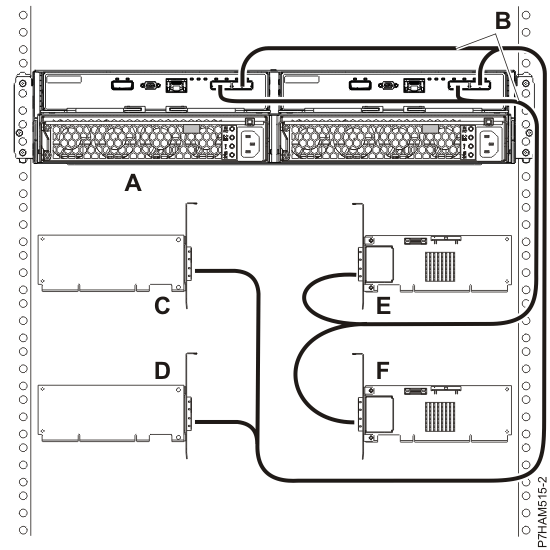
    1. Four single FC 5901 or FC 5278 adapters to one 5887 enclosure via a mode 4 connection.
    2. 5887 enclosure with four sets of six hard disk drives (HDDs).
    • Connection using dual SAS X cables to connect to the 5887 enclosure.
    • Supported only on AIX and Linux systems.
    1. Figure 5. Mode 4 connection of a 5887 enclosure by using X cables to four single SAS adapters
    2. Mode 4 connection of a 5887 enclosure by using X cables to four single SAS adapters
    3. Note: You must match the drive slots that you are using to the connector on the 5887 enclosure, and then to the correct leg of the X cable. For details, see 5887 disk drive enclosure.


    http://www.ibm.com/support/knowledgecenter/en/8286-42A/p8eab/p8eab_82x_84x_slot_details.htm
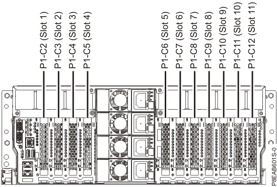


    Rear view of a rack-mounted 8286-41A and 8286-42A system with PCIe slots location codes. 

    'IBM AIX' 카테고리의 다른 글

    AIX H/W RAID Disk replacement  (0) 2016.09.07
    HMC 에서 vio 설치  (0) 2016.09.01
    RMC  (0) 2016.07.18
    sh history  (1) 2016.06.01
    sh history  (0) 2016.06.01

    + Recent posts