https://www.ibm.com/developerworks/community/blogs/meyawi/entry/dlpar_issues_with_cloned_aix_lpar?lang=en
'IBM AIX > VIOS' 카테고리의 다른 글
| VIOS HOW TO (0) | 2016.09.26 |
|---|---|
| vios (0) | 2016.07.19 |
| LPM by IBM (0) | 2016.07.18 |
| LPM (0) | 2016.07.18 |
| VSCSI (0) | 2016.07.18 |
https://www.ibm.com/developerworks/community/blogs/meyawi/entry/dlpar_issues_with_cloned_aix_lpar?lang=en
| VIOS HOW TO (0) | 2016.09.26 |
|---|---|
| vios (0) | 2016.07.19 |
| LPM by IBM (0) | 2016.07.18 |
| LPM (0) | 2016.07.18 |
| VSCSI (0) | 2016.07.18 |
http://www-01.ibm.com/support/docview.wss?uid=isg3T1011040
Cluster Aware AIX (CAA)
http://lparbox.com/how-to/aix/13
http://aixnote.tistory.com/226
http://www-01.ibm.com/support/docview.wss?uid=isg3T1013047
VIO Server Howto
| VIOS DLPAR (0) | 2017.08.31 |
|---|---|
| vios (0) | 2016.07.19 |
| LPM by IBM (0) | 2016.07.18 |
| LPM (0) | 2016.07.18 |
| VSCSI (0) | 2016.07.18 |
Contents
Run IOS commands as root
What is the AIX command behind an ioscli command?
IOS - Information and Maintenance
List all ioscli commands
IOS Version
Apply IOS Fixes
IOS Upgrade Procedure
Reboot the VIO Server
Virtual Devices: Storage
List unmapped disks
List all Disk Mappings
Create a Virtual SCSI Host Adapter
Remove a Virtual SCSI Host Adapter
Assign a Disk/LV to a Virtual SCSI Host Adapter
Unassign a Disk/LV from a Virtual SCSI Host Adapter
Virtual Devices: Fibre Channel
Create a Virtual Fibre Channel Adapter
List Virtual Fibre Channels
List NPIV Capable Ports
Assign a Physical FC Adapter to a Virtual Fibre Channel Adapter
Unassign a Physical FC Adapter from a Virtual Fibre Channel Adapter
Virtual Devices: Network
List Shared Ethernet Adapters
Create a Shared Ethernet Adapter
Enable SEA Load Sharing Mode
Perform a Manual SEA Failover
Show SEA Satus
List Links on Physical Ethernet Adapters
Set a local IP Address
Remove a local IP Address
1. Run IOS commands as root
According to IBM you should never work as root on VIO servers. However, if you login as user padmin and type
oem_setup_env
you get the root credentials (without even been asked for a password).
By default the ioscli commands are not available for the root user. All ioscli commands are in fact calls of /usr/ios/cli/ioscli with the command as argument. You see this if you list the aliases of the padmin user.
Knowing this you can use all ioscli commands as user root by appending /usr/ios/cli/ioscli. Instead of »lsmap -all« you would type
root@vios# /usr/ios/cli/ioscli lsmap -all
If you set an alias
alias i=/usr/ios/cli/ioscli
you could even type
root@vios# i lsmap -all
2. What is the AIX command behind an ioscli command?
If you want to know what AIX command is behind the command you issued as user padmin you can use a special debug mode:
$ export CLI_DEBUG=33
That's the output of the lsnports command in this mode:
$ lsnports
AIX: "/usr/lib/methods/viosmgr -t npiv -f query_fc_ports >/dev/null"
name physloc fabric tports aports swwpns awwpns
fcs0 U789C.001.DQDH231-P1-C2-T1 1 64 64 2048 2047
fcs1 U789C.001.DQDH231-P1-C2-T2 1 64 62 2048 2043
IOS - Information and Maintenance
1. List all ioscli commands
$ help
You can type
$ help <command>
to display a command's syntax, e.g
$ help lsmap
Usage: lsmap {-vadapter ServerVirtualAdapter | -plc PhysicalLocationCode |
-all} [-type BackingDeviceType ... | -net | -npiv ]
[-field FieldName ...] [-fmt delimiter]
lsmap -ams {-vtd PagingDevice | -all}
[-type BackingDeviceType ... ]
[-field FieldName ...] [-fmt delimiter]
lsmap -clustername ClusterName {-all | -hostname}
Displays the mapping between physical and virtual devices.
-all Displays mapping for all the server virtual adapter
devices. Defaults to VSCSI adapter devices.
-clustername Specifies the cluster name.
-hostname Specifies the host name.
-vadapter Specifies the server virtual adapter device
by device name.
-plc Specifies the server virtual adapter device
by physical location code.
-vtd Specifies the (AMS)Active Memory Sharing
Paging Device to be displayed.
-type Specifies to display virtual devices whose backing
device matches the type given.
-net Specifies supplied device is a virtual server
Ethernet adapter.
-npiv Displays NPIV binding information.
-ams Displays (AMS)Active Memory Sharing paging space
device information.
-field Specifies a list of fields to be displayed.
-fmt Divides output by a user-specified delimiter.
2. IOS Version
$ ioslevel
2.2.0.10-FP-24
3. Apply IOS Fixes
Put the IOS fixes somewhere in a local directory or on an NFS server (e.g. /mnt/iosfixes). Then run
$ updateios -dev /mnt/iosfixes -accept
4. IOS Upgrade Procedure
It is highly recommended first to clone the running installations to free disks (here: hdisk2 and hdisk3). That way we can always go back to the old working installation:
$ oem_setup_env
# alt_disk_copy -B -d "hdisk2 hdisk3"
# exit
Read the release notes. You may need to upgrade the VIO server in two steps (e.g. first to 2.2.2.1 and than further to 2.2.2.5).
Then put the IOS upgrade packages somewhere in a local directory or on an NFS server (e.g. /updates/2.2.2.5) and run
$ updateios -commit
$ updateios -dev /updates/2.2.2.5 -accept -install
$ shutdown -restart
5. Reboot the VIO Server
$ shutdown -restart
Virtual Devices: Storage
1. List unmapped disks
$ lspv -free
NAME PVID SIZE(megabytes)
hdisk24 none 8631
hdisk25 none 8631
hdisk26 none 8631
hdisk27 none 8631
Warning: If you use vendor specific device drivers (such as the SDD or EMC drivers) you see all hdisks as free. You have to limit the list to your logical devices, e.g.
$ lspv -free | grep vpath
2. List all Disk Mappings
$ lsmap -all
SVSA Physloc Client Partition ID
--------------- -------------------------------------------- ------------------
vhost1 U9117.570.65E12FB-V1-C102 0x0000000a
VTD vtscsi1
LUN 0x8100000000000000
Backing device hdisk6
Physloc U7879.001.DQDHXYN-P1-C4-T1-W50050763041302AA-L4021400000000000
VTD vtscsi8
LUN 0x8200000000000000
Backing device hdisk14
Physloc U7879.001.DQDHXYN-P1-C4-T1-W50050763041302AA-L4031400100000000
VIOS Profile: Add Virtual SCSI Adapter
3. Create a Virtual SCSI Host Adapter
This has to done on the HMC for the profile of the VIO server: You create a new Virtual SCSI Host-Adapter and assign it only to your client LPAR.
The same slot ID should then be assigned to a new client adapter in the client LPAR's profile.
You can do these steps dynamically to avoid a restart of the VIO server. Use the Dynamic Logical Partitioning option for that. If you go for the dynamic option don't forget to do the same assignments in the profiles aswell, otherwise your LPAR loses all storage after a new start of the VIOS!
After dynamically adding the server hostadapters you have to rerun the configuration mamager before you can see the new vhost device:
$ cfgdev
4. Remove a Virtual SCSI Host Adapter
$ rmdev -dev vhostX [ -recursive ]
The option »-recursive« can be used to remove all still attached child devices.
Then remove the adapters dynamically from the VIO server aswell as from the VIOS' profile.
5. Assign a Disk/LV to a Virtual SCSI Host Adapter
To map hdisk22 to vhost1 just type
$ mkvdev -vdev hdisk22 -vadapter vhost1
vtscsi19 available
The VIO server assigns the next free number (19 here) and creates the mapping device vtscsi19. But you can specify your own name for the mapping device by making use of the »-dev« option:
$ mkvdev -vdev hdisk22 -dev vthdisk22_barney -vadapter vhost1
vthdisk22_barney available
If you use LVs rather than whole disks or LUNs the same rules apply:
# default mapping device
$ mkvdev -vdev lpar21_lv03 -vadapter vhost1
vtscsi19 available
# custom mapping device
$ mkvdev -vdev lpar21_lv03 -dev vtdisk21_lv03 -vadapter vhost1
vtdisk21_lv03 available
6. Unassign a Disk/LV from a Virtual SCSI Host Adapter
$ rmvdev -vtd vtscsiXX
Virtual Devices: Fibre Channel
IBM introduced the support of NPIV technology with VIOS (Virtual I/O Sever) 2.1 with a client AIX running either AIX 5.3 TL9 or later, or AIX 6.1 TL2 or later, or AIX 7.1. Earlier releases are not supported.
1. Create a Virtual Fibre Channel Adapter
This has to done on the HMC for the profile of the VIO server: You create a new Virtual Server Fibre Channel adapter and assign it to only one client LPAR.
The same slot ID should then be assigned to a new Client Fibre Channel adapter in the client LPAR's profile.
2. List Virtual Fibre Channels
$ lsmap -all -npiv
Name Physloc ClntID ClntName ClntOS
------------- ---------------------------------- ------ -------------- -------
vfchost0 U8203.E4A.05A6DD1-V1-C41 3 mylpar6 AIX
Status:LOGGED_IN
FC name:fcs1 FC loc code:U789C.001.DQDH231-C3-T2
Ports logged in:2
Flags:a<LOGGED_IN,STRIP_MERGE>
VFC client name:fcs0 VFC client DRC:U8203.E4A.05A6DD1-V3-C41-T1
Name Physloc ClntID ClntName ClntOS
------------- ---------------------------------- ------ -------------- -------
vfchost1 U8203.E4A.05A6DD1-V1-C43 4 mylpar8 AIX
Status:LOGGED_IN
FC name:fcs1 FC loc code:U789C.001.DQDH231-C3-T2
Ports logged in:2
Flags:a<LOGGED_IN,STRIP_MERGE>
VFC client name:fcs0 VFC client DRC:U8203.E4A.05A6DD1-V4-C43-T1
3. List NPIV Capable Ports
NPIV = N_port ID Virtualization
$ lsnports
name physloc fabric tports aports swwpns awwpns
fcs0 U789C.001.DQDH231-P1-C2-T1 1 64 64 2048 2047
fcs1 U789C.001.DQDH231-P1-C2-T2 1 64 62 2048 2043
4. Assign a Physical FC Adapter to a Virtual Fibre Channel Adapter
$ vfcmap -vadapter vfchost0 -fcp fcs1
5. Unassign a Physical FC Adapter from a Virtual Fibre Channel Adapter
There isn't a separate command for this action - you just leave the argument after -fcp empty:
$ vfcmap -vadapter vfchost0 -fcp
Virtual Devices: Network
1. List Shared Ethernet Adapters
$ lsmap -all -net
SVEA Physloc
------ --------------------------------------------
ent12 U9117.570.65E12FB-V2-C20-T1
SEA ent13
Backing device ent3
Physloc U7311.D20.651372C-P1-C01-T2
2. Create a Shared Ethernet Adapter
To create a Shared Ethernet Adapter (SEA) you need:
a physical adapter as backend: <PHYS>
a virtual adapter as defined in the VIOS' profile: <VIRT>
an internal VLAN ID: <VLAN>
If you use the Shared Ethernet Adapter Failover capability of recent IOS releases you also need
a second virtual adapter as defined in the VIOS' profile: <CONT>
for the control channel:
# simple:
$ mkvdev -sea <PHYS> -vadapter <VIRT> -default <VIRT> -defaultid <VLAN>
# Shared Ethernet Adapter Failover:
$ mkvdev -sea <PHYS> -vadapter <VIRT> -default <VIRT> -defaultid <VLAN> -attr ha_mode=auto ctl_chan=<CONT>
Example: To create a Shared Ethernet Adapter on top of an virtual adapter ent11 using VLAN 20, the physical adapter ent2 as backend, and the virtual adapter ent13 for the control channel type:
$ mkvdev -sea ent2 -vadapter ent11 -default ent11 -defaultid 20 -attr ha_mode=auto ctl_chan=ent13
3. Enable SEA Load Sharing Mode
First on the primary SEA, then on the secondary:
$ chdev -dev <SEA> -attr ha_mode=sharing
4. Show SEA Satus
Let's say for the SEA ent20:
$ entstat -all ent20 | grep '^[ ]*State'
State: PRIMARY
Other possible states: BACKUP, PRIMARY_SH, BACKUP_SH. The states PRIMARY_SH and BACKUP_SH are indicating that Load Sharing Mode has been enabled.
5. Perform a Manual SEA Failover
To perform a failover for the SEA ent20 go to the active side ("State: PRIMARY") and type:
$ chdev -dev ent20 -attr ha_mode=standby
The SEA on the other VIO server automatically becomes active. To switch back you would type
$ chdev -dev ent20 -attr ha_mode=auto
6. List Links on Physical Ethernet Adapters
$ netstat -cdlistats | grep -Ei "\(ent|media|link status"
ETHERNET STATISTICS (ent3) :
Link Status : Up
Media Speed Selected: 100 Mbps Full Duplex
Media Speed Running: 100 Mbps Full Duplex
7. Set a local IP Address
To configure an local IP 192.168.1.2 address to en0 use
$ mktcpip -hostname <HOSTNAME> \
-inetaddr 192.168.1.2 \
-interface en0 -start \
-netmask 255.255.255.0 \
-gateway <GATEWAY>
8. Remove a local IP Address
If you want to remove the IP configuration from en0, type
$ rmtcpip -interface en0
(c) unixwerk Content is available under the BSD Documentation License.
| VIOS DLPAR (0) | 2017.08.31 |
|---|---|
| VIOS HOW TO (0) | 2016.09.26 |
| LPM by IBM (0) | 2016.07.18 |
| LPM (0) | 2016.07.18 |
| VSCSI (0) | 2016.07.18 |
http://www.ibm.com/developerworks/aix/library/au-LPM_troubleshooting/
Live Partition Mobility (LPM) was introduced on Power6. It helps to avoid downtime during VIOS and firmware updates when migrating to other frames. LPM also reduces the amount of work that is required while creating a new LPAR and set-up, which is required for the application.
A majority of customers perform LPM activities on a daily basis, and many may not know the exact procedure or what is taking place. This article shows steps to overcome or fix LPM issues.

Things to remember about LPM are that it migrates running partitions from one physical server to another while maintaining complete transactional integrity and transfers the entire environment: processor state, memory, virtual devices, and connected users. Partitions may also migrate while powered off (inactive migration), and the operating system and application must reside on shared storage.
You must have a minimum of two machines, a source and a destination, on POWER6 or higher with the Advanced Power Virtualization Feature enabled. The operating system and application must reside on a shared external storage (Storage Area Network). In addition to these hardware requirements, you must have:
Your virtual I/O servers (VIOS) must have a Shared Ethernet Adapter (SEA) configured to bridge to the same Ethernet network which the mobile partition uses. It must be capable of providing virtual access to all the disk resources which the mobile partition uses (NPIV or vSCSI). If you are using vSCSI, then the virtual target devices must be physical disks (not logical volumes).
You must be at AIX version 5.3J or later, VIOS version 1.4 or later, HMC V7R310 or later and the firmware at efw3.1 or later.

The following describes the general LPM depiction in Figure 2:
Before doing LPM, we need to verify the availability of resources on both the source and destination side. If validation fails with some error, then we have to fix it to proceed further. Sometimes validation may end up with warning messages which can be ignored.
Figure 3 shows you how to validate the LPAR with the HMC GUI.
From the System management -> Servers -> Trim screen, select the LPAR name: Operations -> Mobility -> Validate

The validate screen, shown in Figure 4, shows that upt0052 LPAR is validated for migration from trsim to dash, and if needed, we have to specify the destination HMC.

Figure 5 show that the LPM has ended with a warning message, ignore the message and select Close to continue with the migration.

Figure 6, the Partition Migration Validation screen, shows that the information is selected to set up a migration of the partition to a different managed system. Select Migrate to verify the information.

When the migration completes, as shown in Figure 7, select Close

To validate the LPM in local HMC, enter the following:
migrlpar -o v -m [source cec] -t [target cec] -p [lpar to migrate]
To validate the LPM in the Remote HMC, type:
migrlpar -o v -m [source cec] -t [target cec] -p [lpar to migrate] \
> --ip [target hmc] -u [remote user]
Note, you may prefer to use the hscroot command as the remote user.
Use the following migration command for LPM in the local HMC:
migrlpar -o m -m [source cec] -t [target cec] -p [lpar to migrate]
The following migration command for LPM is used with the remote HMC:
migrlpar -o m -m [source cec] -t [target cec] -p [lpar to migrate] \
> --ip [target hmc] -u [remote user]
In case of MPIO (Multipath IO) failure of a LPAR due to configuration issues between source and destination, type the following to proceed (if applicable):
migrlpar -o m -m wilma -t visa -p upt07 --redundantpgvios 0 -n upt07_n
oams_npiv -u hscroot --vlanbridge 2 --mpio 2 -w 60 -d 5 -v -i
"source_msp+name=wilmav2,dest_msp_name=visav2" --ip destiny4
This section covers various errors messages you might encounter and ways to correct them.
mkauthkey error displays:hscroot@destiny4:~> migrlpar -o v -m trim -p UPT0052 --ip hmc-arizona -u hscroot -t arizona HSCL3653 The Secure Shell (SSH) communication configuration between the source and target Hardware Management Consoles has not been set up properly for user hscroot. Please run the mkauthkeys command to set up the SSH communication authentication keys.
To overcome this error, type the following:
hscroot@destiny4:~> mkauthkeys -g --ip hmc-arizona -u hscroot
Enter the password for user hscroot on the remote host hmc-arizona
hscroot@destiny4:~> migrlpar -o v -m trim -p
    UPT0052 --ip hmc-liken -u hscroot -t wilma

HSCLA318 The migration command issued to the destination HMC failed with the
following error: HSCLA335 The Hardware Management Console for the destination
managed system does not support one or more capabilities required to perform
this operation. The unsupported capability codes are as follows: AME_capability
hscroot@destiny4:~>
To correct this error either migrate to POWER7 or remove the AME and then migrate.
hscroot@hmc-liken:~> migrlpar -o v -m wilma -t visa --ip destiny4 -u hscroot -p
upt0060 --mpio 2

Errors:
HSCLA304 A suitable shared memory pool for the mobile partition was not found on the
destination managed system. In order to support the mobile partitions, the
destination managed system must have a shared memory pool that can accommodate the
partition's entitled and maximum memory values, as well ad its redundant paging
requirements. If the destination managed system has a shared memory pool, inability
to support the mobile shared memory partition can be due to lack of sufficient memory
in the pool, or lack of a paging space device in the pool that meets the mobile
partition's redundancy and size requirements.

Details:
HSCLA297 The DLPAR Resource Manager (DRM) capability bits )x) for mover service
partition (MSP) visav2 indicate that partition mobility functions are not supported
on the partition.
HSCLA2FF An internal Hardware Management Console error has occurred. If this error
persists, contact your service representative.
To correct this error do either, or both, of the following:
hscroot@destiny4:~> migrlpar -o v -m dash -t arizona --ip hmc-arizona -u hscroot
-p upt0053

Errors:
HSCLA224 The partition cannot be migrated because it has been designated to use a
processor compatibility level that is not supported by the destination managed
system. Use the HMC to configure a level that is compatible with the destination
managed system.
The solution for the above error could be one of the following:
The steps to change processor mode in HMC GUI are:
hscroot@destiny4:~> migrlpar -o v -m dash -t arizona --ip hmc-arizona -u hscroot
-p upt0058

Errors:
The migrating partition's virtual SCSI adapter cannot be hosted by the existing
virtual I/O server (VIOS) partitions on the destination managed system. To
migrate the partition, set up the necessary VIOS hosts on the destination
managed system, then try the operation again.

Details:
HSCLA356 The RMC command issued to partition arizona failed. This means that
destination VIOS partition arizona2 cannot host the virtual adapter 6 on the
migrating partition.

HSCLA29A The RMC command issued to partition failed.
The partition command is:
migmgr -f find_devices -t vscsi -C 0x3 -d 1
The RMC return code is:
0
The OS command return code is:
85
The OS standard out is:
Running method '/usr/lib.methods/mig_vscsi
85
The OS standard err is:

The search was performed for the following device descriptions:
        <v-scsi-host>
                 <generalInfo>
                    <version>2.0 </version>
                    <maxTransfer>262144</maxTransfer>
                    <minVIOSpatch>0</minVIOSpatch>
                    <minVIOScompatability>1</minVIOScompatability>
                    <effectiveVIOScompatability>1</effectiveVIOScompatability>
                  <generalInfo>
                  <ras>
                        <partitionID>2</partitionID>
                   </ras>
                   <virtDev>
                            <vLUN>
                                        <LUA>0x81000000000000000</LUA>
                                        <LUNState>0</LUNState>
                                        <clientReserve>no</clientReserve>
                                        <AIX>
                                                <type>vdasd</type>
                                                <connWhere>1</connWhere>
                                        </AIX>
                            </vLUN>
                            <blockStirage>
                                        <reserveType>NI_RESERVE</reserveType>
                                        <AIX>

                           <udid>261120017380003D30194072810XIV03IBMfcp</udid>
                                                <type>UDID</type>
                                        </AIX>
                            </blockStirage>
                    </virtDev>
     </v-scsi-host>
And, the solution is as follows:
In cases where the mapping is correct, and you are still getting the same error, it may be due to having different types of FC adapters between source and destination MSP. For mapping methods, refer to last Note section of "Troubleshooting".
hscpe@destiny4:~> migrlpar -o v -m dash -t wilma -p upt0053 --ip defiant2 -u
hscroothmc-arizona -u hscroot
Errors:
The partition cannot be migrated because the processing resources it requires
exceeds the available processing resources in the destination managed system's
shared processor pool. If possible, free up processing resources from that shared
processor pool and try the operation again.
And the solution is:
hscpe@destiny4:~> migrlpar -o v -m extra5 -t dash -p upt0027
Errors:
There is not enough memory: Obtained: 2816, Required: 4608.  Check that there is
enough memory available to activate the partition. If not, create a new profile or
modify the existing profile with the available resources, then activate the
partition. If the partition must be activated with these resources, deactivate any
running partition or partitions using the resource, then activate this partition.
And, the solution is either:
If the RMC (Resource Monitoring and Control) connection is not established among the source, target VIOS's and LPAR, then we may get following error:
hscpe@destiny4:~> migrlpar -o v -m dash -t trim -p upt0053
Errors:
The operation to check partition upt0053 for migration readiness has failed.
The partition command is:
drmgr -m -c pmig -p check -d 1
The partition standard error is:

HSCLA257 The migrating partition has returned a failure response to the HMC's
request to perform a check for migration readiness. The migrating partition in
not ready for migration at this time. Try the operation again later.

Details:
HSCLA29A  The RMC command issued to partition upt0053 failed. \
The partition commend is:
drmgr -m -c pmig -p check -d 1
The RMC return code is:
1141
The OS command return code is:
0
The OS standard out is:
Network interruption occurs while RMC is waiting for the execution of the command
on the partition to finish.
Either the partition has crashed, the operation has caused CPU starvation, or
IBM.DRM has crashed in the middle of the operation.
The operation could have completed successfully. (40007) (null)
The OS standard err is:hscroote@hmc-liken:~> migrlpar -o v -m wilma -t visa --ip destiny4 -u hscroot -p upt0060 Errors: HSCLA340 The HMC may not be able to replicate the source multipath I/O configuration for the migrating partition's virtual I/O adapters on the destination. This means one or both of the following: (1) Client adapters that are assigned to different source VIOS hosts may be assigned to a single VIOS host on the destination; (2) Client adapters that are assigned to a single source VIOS host may be assigned to different VIOS hosts on the destination. You can review the complete list of HMC-chosen mappings by issuing the command to list the virtual I/O mappings for the migrating partition. HSCLA304 A suitable shared memory pool for the mobile partition was not found on the destination managed system. In order to support the mobile partition, the destination managed system must have a shared memory pool that can accommodate the partition's entitled and maximum memory values, as well as its redundant paging requirements. If the destination managed system has a shared memory pool, inability to support the mobile shared memory partition can be due to lack of sufficient memory in the pool, or lack of a paging space device in the pool that meets the mobile partition's redundancy and size requirements. Details: HSCLA297 The DLPAR Resource Manager (DRM) capability bits 0x0 for mover service partition (MSP) visav2 indicate that partition mobility functions are not supported on the partition. HSCLA2FF An internal Hardware Management Console error has occurred. If this error persists, contact your service representative. Warning: HSCLA246 The HMC cannot communicate migration commands to the partition visav2. Either the network connection is not available or the partition does not have a level of software that is capable of supporting partition migration. Verify the correct network and migration setup of the partition, and try the operation again.
The solution is:
If above solution is not feasible to implement then:
--mpio 2 with the migrlpar command. By using this, we may lose dual VIOS setup for MPIO disks. Generally this is not a recommended solution by PowerVM.hscroote@hmc-liken:~> migrlpar -o v -m wilma -t visa --ip destiny4 -u hscroot -p upt0060 Errors: HSCLA340 The HMC may not be able to replicate the source multipath I/O configuration for the migrating partition's virtual I/O adapters on the destination. This means one or both of the following: (1) Client adapters that are assigned to different source VIOS hosts may be assigned to a single VIOS host on the destination; (2) Client adapters that are assigned to a single source VIOS host may be assigned to different VIOS hosts on the destination. You can review the complete list of HMC-chosen mappings by issuing the command to list the virtual I/O mappings for the migrating partition. HSCLA304 A suitable shared memory pool for the mobile partition was not found on the destination managed system. In order to support the mobile partition, the destination managed system must have a shared memory pool that can accommodate the partition's entitled and maximum memory values, as well as its redundant paging requirements. If the destination managed system has a shared memory pool, inability to support the mobile shared memory partition can be due to lack of sufficient memory in the pool, or lack of a paging space device in the pool that meets the mobile partition's redundancy and size requirements. Details: HSCLA297 The DLPAR Resource Manager (DRM) capability bits 0x0 for mover service partition (MSP) visav2 indicate that partition mobility functions are not supported on the partition. HSCLA2FF An internal Hardware Management Console error has occurred. If this error persists, contact your service representative. Warning: HSCLA246 The HMC cannot communicate migration commands to the partition visav2. Either the network connection is not available or the partition does not have a level of software that is capable of supporting partition migration. Verify the correct network and migration setup of the partition, and try the operation again.
When we verify in VIOS:
lsmap -all -npiv
Name        Physloc                           ClntID  ClntName     ClntOS
----------- --------------------------------- ------- ------------ ------
vfchost3    U9117.MMB.100302P-V1-C14             5      upt0052      AIX

Status:LOGGED_IN
FC name:fcs0                   FC  loc code:U78C0.001.DBJ0563-P2-C1-T1
Ports logged in:35
Flags:a<LOGGED_IN,STRIP_MERGE>
VFC client name:fcs1            VFC client DRC:U8233.E8B.100244P-V5-C4-T1
Name        Physloc                           ClntID  ClntName     ClntOS
----------- --------------------------------- ------- ------------ ------
vfchost3    U9117.MMB.100302P-V1-C13

Status:LOGGED_IN
FC name:fcs0                   FC  loc code:U78C0.001.DBJ0563-P2-C1-T1
Ports logged in:0
Flags:4<NOT_LOGGED>
VFC client name:                VFC client DRC
Here the problem is vfchost3 and vfchost8 both mapped to same host (upt0058) and both mapped to same physical FC(fcs0). This is not the recommended setup. To fix this use either of these methods:
hscroot@guandu5:~> migrlpar -o v -m flrx -t dash --ip destiny4  -u hscroot -p
    upt0064
HSCLA319 The migrating partition's virtual fibre channel client adapter 4
cannot be hosted by the existing Virtual I/O Server (VIOS) partitions on
the destination managed system. To migrate the partition, set up the
necessary VIOS host on the destination managed system, then try the
operation again.
HSCLA319 The migrating partition's virtual fibre channel client adapter 3
cannot be hosted by the existing Virtual I/O Server (VIOS) partitions on
the destination managed system. To migrate the partition, set up the
necessary VIOS host on the destination managed system, then try the
operation again.

Details:
HSCLA356 The RMC command issued to partition dashv1 failed. This means that
destination VIOS partition dashv1 cannot host the virtual adapter 4 on the
migrating partition.
HSCLA29A The RMC command issued to partition dashv1 failed.
The partition command is:
migmgr -f find_devices -t vscsi -C 0x3 -d 1
The RMC return code is:
0
The OS command return code is:
69
The OS standard out is:
Running method '/usr/lib/methods/mig_vscsi'
69

The OS standard err is:


The search was performed for the following device description:
      <vfc-server>
               <generalInfo>
                   <version>2.0 </version>
                   <maxTransfer>1048576</maxTransfer>
                   <minVIOSpatch>0</minVIOSpatch>
                   <minVIOScompatability>1</minVIOScompatability>
                   <effectiveVIOScompatability>-1</effectiveVIOScompatability>
                   <numPaths>1</numPaths>
                   <numPhysAdapPaths>1</numPhysAdapPaths>
                   <numWWPN>34</numWWPN>
                   <adpInterF>2</adpInterF>
                   <adpCap>5</adpCap>
                   <linkSpeed>400</linkSpeed>
                   <numIniat>6</numIniat>
                   <activeWWPN>0xc0507601a6730036</activeWWPN>
                   <inActiveWWPN>0xc0507601a6730037</inActiveWWPN>
                   <nodeName>0xc0507601a6730036</nodeName>
                   <streamID>0x0</streamID>
                <generalInfo>
                  <ras>
                        <partitionID>1</partitionID>
                   </ras>
                  <wwpn_list>
                                <wwpn>0x201600a0b84771ca</wwpn>
                                <wwpn>0x201700a0b84771ca</wwpn>
                                <wwpn>0x202400a0b824588d</wwpn>
                                <wwpn>0x203400a0b824588d</wwpn>
                                <wwpn>0x202500a0b824588d</wwpn>
                                <wwpn>0x203500a0b824588d</wwpn>
                                <wwpn>0x5005076303048053</wwpn>
                                <wwpn>0x5005076303098053</wwpn>
                                <wwpn>0x5005076303198053</wwpn>
                                <wwpn>0x500507630319c053</wwpn>
                                <wwpn>0x500507630600872d</wwpn>
                                <wwpn>0x50050763060b872d</wwpn>
                                <wwpn>0x500507630610872d</wwpn>
                                <wwpn>0x5005076306ib872d</wwpn>
                                <wwpn>0x500a098587e934b3</wwpn>
                                <wwpn>0x500a098887e934b3</wwpn>
                                <wwpn>0x20460080e517b812</wwpn>
                                <wwpn>0x20470080e517b812</wwpn>
                                <wwpn>0x201400a0b8476a74</wwpn>
                                <wwpn>0x202400a0b8476a74</wwpn>
                                <wwpn>0x201500a0b8476a74</wwpn>
                                <wwpn>0x202500a0b8476a74</wwpn>
                                <wwpn>0x5005076304108e9f</wwpn>
                                <wwpn>0x500507630410ce9f</wwpn>
                                <wwpn>0x50050763043b8e9f</wwpn>
                                <wwpn>0x50050763043bce9f</wwpn>
                                <wwpn>0x201e00a0b8119c78</wwpn>
                                <wwpn>0x201f00a0b8119c78</wwpn>
                                <wwpn>0x5001738003d30151</wwpn>
                                <wwpn>0x5001738003d30181</wwpn>
                                <wwpn>0x5005076801102be5</wwpn>
                                <wwpn>0x5005076801102dab</wwpn>
                                <wwpn>0x5005076801402be5</wwpn>
                                <wwpn>0x5005076801402dab</wwpn>
                    </wwpn_list>

   <vfc-server>
The solution can be any one of the following (or it may fail due to other mismatching characteristic of target FC adapters):
Sometimes the configuration log at the time of validation or migration is required to debug the errors. To get the log, run the following command from source MSP:
alog -t cfg -o > cfglog
NPIV mapping steps for LPM:
vSCSI mapping steps for LPM:
As per the prerequisites for LPM section for doing LPM, the LPAR should not have any physical adapters, but if it is a POWER7, it can have Host Ethernet Adapter (Integrated Virtualized Ethernet) attached to it. However, for a POWER7 LPAR which you want to migrate to other POWER7 can have HEA attached to it, but we must create etherchannel on a newly created virtual adapter and HEA in aggregation mode. When we migrate at the target we see only virtual adapter configured with IP and etherchannel; HEA will not be migrated. Also, make sure the VLANs used in virtual adapters to create etherchannel are added to both source and target VIOS.
Before LPM:
# lsdev -Cc adapter
ent0  Available       Logical Host Ethernet Port (lp-hea)
ent1  Available       Logical Host Ethernet Port (lp-hea)
ent2  Available       Logical Host Ethernet Port (lp-hea)
ent3  Available       Logical Host Ethernet Port (lp-hea)
ent4  Available       Virtual I/O Ethernet Port (l-lan)
ent7  Available       Virtual I/O Ethernet Port (l-lan)
ent6  Available       Virtual I/O Ethernet Port (l-lan)
ent7  Available       Virtual I/O Ethernet Port (l-lan)
ent8  Available       EtherChannel / 802.3ad Link Aggregation
ent9  Available       EtherChannel / 802.3ad Link Aggregation
ent10 Available       EtherChannel / 802.3ad Link Aggregation
ent11 Available       EtherChannel / 802.3ad Link Aggregation
fcs0  Available C3-T1 Virtual Fibre Channel Adapter
fcs1  Available C3-T1 Virtual Fibre Channel Adapter
lhea0 Available       Logical Host Ethernet Adapter (l-hea)
lhea1 Available       Logical Host Ethernet Adapter (l-hea)
vsa0  Available       LPAR Virtual Serial Adapter
[root@upt0017] /
In this case doing LPM is also a bit different compared to the earlier method; this has to be done from the LPAR using smitty (also called client side LPM), not from HMC. But, LPAR must install with SSH fileset to do LPM through smitty.
openssh.base.client
openssh.base.server
openssh.license
openssh.man.en_US
openssl.base
openssl.license
openssl.man.en_US
Use smitty to migrate an Power7 LPAR with HEA. Smit --> Applications will be the first step to do LPM from smitty.
# smit

System Management
Move cursor to desired item and press Enter

  Software Installation and Maintenance
  Software License Management
  Mange Edition
  Devices
  System Storage Management  *Physical & Logical Storage)
  Security & User
  Communication Applications and Services
  Workload Partition Administration
  Print Spooling
  Advanced Accounting
  Problem Determination
  Performance & Resource Scheduling
  System Environments
  Processes & Subsystems
  Applications
  Installation Assistant
  Electronic Service Agent
  Cluster Systems Management
  Using SMIT (information only)
After selecting "Applications", then select "Live Partition Mobility with Host Ethernet Adapter (HEA)" to proceed.
Move cursor to desired item and press Enter

Live Partition Mobility with Host Ethernet Adapter (HEA)
Next enter the required fields such as source and destination HMC and HMC users, source and destination managed system names, LPAR name.
                   Live Partition Mobility with Host Ethernet Adapter (HEA)

Type or select values in the entry fields.
Press Enter AFTER making all desired changes

                                                     [Entry Fields]
* Source HMC Hostname or IP address                [destinty2]
* Source HMC Username             [hscroot]
* Migration between two HMCs                         no
        Remote HMC hostname or IP address          [ ]
        Remote HMC Username                        [ ]
*Source System                                     [link]
* Destination System                               [king]
* Migrating Partition Name                         [upt0017]
* Migration validation only                          yes
Once the successful migration the smitty command output says OK.
Command Status

Command: OK            stdout: yes           Stderr: no
Before command completion, additional instruction may appear below.

Setting up SSH credentials wit destinty2
If prompted for a password, please enter password for user hscroot on HMC destinty2
Verifying EtherChannel configuration ...
Modifying EtherChannel configuration for mobility ...
Starting partition mobility process. This process is complete.
DO NOT halt or kill the migration process. Unexpected results may occur if the migration
process is halted or killed.
Partition mobility process is complete. The partition has migrated.
After successful LPM, all HEA's will be in defined state, but still the etherchannel between HEA and Virtual adapter exists and IP is still configured on Etherchannel.
[root@upt0017] /
# lsdev -Cc adapter

ent0   Defined             Logical Host Ethernet Port  (lp-hea)
ent1   Defined             Logical Host Ethernet Port  (lp-hea)
ent2   Defined             Logical Host Ethernet Port  (lp-hea)
ent3   Defined             Logical Host Ethernet Port  (lp-hea)
ent4   Available           Virtual I/O Ethernet Adapter  (l-lan)
ent5   Available           Virtual I/O Ethernet Adapter  (l-lan)
ent6   Available           Virtual I/O Ethernet Adapter  (l-lan)
ent7   Available           Virtual I/O Ethernet Adapter  (l-lan)
ent8   Available           EtherChannel  /  IEEE 802.3ad Link Aggregation
ent9   Available           EtherChannel  /  IEEE 802.3ad Link Aggregation
ent10  Available           EtherChannel  /  IEEE 802.3ad Link Aggregation
ent11  Available           EtherChannel  /  IEEE 802.3ad Link Aggregation
fcs0   Available  C3-T1    Virtual Fibre Channel Client Adapter
fcs1   Available  C4-T1    Virtual Fibre Channel Client Adapter
lhea0  Defined             Logical Host Ethernet Adapter  (l-hea)
lhea1  Defined             Logical Host Ethernet Adapter  (l-hea)
vsa0   Available           LPAR Virtual Serial Adapter
[root@upt0017] /
# netstat -i
Name  Mtu    Network      Address            Ipkts   Ierrs        Opkts  Oerrs  Coll
en8   1500   link#2      0.21.5E.72.AE.40    9302210    0       819878     0       0
en8   1500   10.33       upt0017.upt.aust    9302210    0       819978     0       0
en9   1500   link#3      0.21.5e.72.ae.52      19667    0          314     2       0
en9   1500   192.168.17  upt0017e0.upt.au      19667    0          314     2       0
en10  1500   link#4      0.21.5e.72.ae.61      76881    0         1496     0       0
en10  1500   192.168.18  upt0017g0.upt.au      76881    0         1496     0       0
en11  1500   link#5      0.21.5e.72.ae.73       1665    0         2200     2       0
en11  1500   192.168.19  upt0017d0.upt.au       1665    0         2200     2       0
lo0   16896  link#1                          1660060    0       160060     0       0
lo0   16896  loopback    localhost ''        1660060    0       160060     0       0
lo0   16896  ::1%1                           1660060    0       160060     0       0
[root@upt0017] /
#
Additional enhancements are:

VIRTUAL SCSI
Virtual SCSI is based on a client/server relationship. The Virtual I/O Server owns the physical resources and acts as server or, in SCSI terms, target device. The client logical partitions access the virtual SCSI backing storage devices provided by the Virtual I/O Server as clients.
Virtual SCSI server adapters can be created only in Virtual I/O Server. For HMC-managed systems, virtual SCSI adapters are created and assigned to logical partitions using partition profiles.
The vhost SCSI adapter is the same as a normal SCSI adapter. You can have multiple disks assigned to it. Usually one virtual SCSI server adapter mapped to one virtual SCSI client adapter will be configured, mapping backing devices through to individual LPARs. It is possible to map these virtual SCSI server adapters to multiple LPARs, which is useful for creating virtual optical and/or tape devices, allowing removable media devices to be shared between multiple client partitions.
on VIO server:
root@vios1: / # lsdev -Cc adapter
vhost0 Available Virtual SCSI Server Adapter
vhost1 Available Virtual SCSI Server Adapter
vhost2 Available Virtual SCSI Server Adapter
The client partition accesses its assigned disks through a virtual SCSI client adapter. The virtual SCSI client adapter sees the disks, logical volumes or file-backed storage through this virtual adapter as virtual SCSI disk devices.
on VIO client:
root@aix21: / # lsdev -Cc adapter
vscsi0 Available Virtual SCSI Client Adapter
root@aix21: / # lscfg -vpl hdisk2
hdisk2 U9117.MMA.06B5641-V6-C13-T1-L890000000000 Virtual SCSI Disk Drive
In SCSI terms:
virtual SCSI server adapter: target
virtual SCSI client adapter: initiator
(Analogous to server client model, where client is the initiator.)
Physical disks presented to the Virtual I/O Server can be exported and assigned to a client partition in a number of different ways:
- The entire disk is presented to the client partition.
- The disk is divided into several logical volumes, which can be presented to a single client or multiple different clients.
- With the introduction of Virtual I/O Server 1.5, files can be created on these disks and file-backed storage can be created.
- With the introduction of Virtual I/O Server 2.2 Fixpack 24 Service Pack 1 logical units from a shared storage pool can be created.
The IVM and HMC environments present 2 different interfaces for storage management under different names. Storage Pool interface under IVM is essentially the same as LVM under HMC. (These are used sometimes interchangeably.) So volume group can refer to both volume groups and storage pools, and logical volume can refer to both logical volumes and storage pool backing devices.
Once these virtual SCSI server/client adapter connections have been set up, one or more backing devices (whole disks, logical volumes or files) can be presented using the same virtual SCSI adapter.
When using Live Partition Mobility storage needs to be assigned to the Virtual I/O Servers on the target server.
----------------------------
Number of LUNs attached to a VSCSI adapter:
VSCSI adapters have a fixed queue depth that varies depending on how many VSCSI LUNs are configured for the adapter. There are 512 command elements of which 2 are used by the adapter, 3 are reserved for each VSCSI LUN for error recovery and the rest are used for IO requests. Thus, with the default queue_depth of 3 for VSCSI LUNs, that allows for up to 85 LUNs to use an adapter: (512 - 2) / (3 + 3) = 85.
So if we need higher queue depths for the devices, then the number of LUNs per adapter is reduced. E.G., if we want to use a queue_depth of 25, that allows 510/28= 18 LUNs. We can configure multiple VSCSI adapters to handle many LUNs with high queue depths, each requiring additional memory. One may have more than one VSCSI adapter on a VIOC connected to the same VIOS if you need more bandwidth.
Also, one should set the queue_depth attribute on the VIOC's hdisk to match that of the mapped hdisk's queue_depth on the VIOS.
Note that to change the queue_depth on an hdisk at the VIOS requires that we unmap the disk from the VIOC and remap it back, or a simpler approach is to change the values in the ODM (e.g. # chdev -l hdisk30 -a queue_depth=20 -P) then reboot the VIOS.
----------------------------
File Backed Virtual SCSI Devices
Virtual I/O Server (VIOS) version 1.5 introduced file-backed virtual SCSI devices. These virtual SCSI devices serve as disks or optical media devices for clients.
In the case of file-backed virtual disks, clients are presented with a file from the VIOS that it accesses as a SCSI disk. With file-backed virtual optical devices, you can store, install and back up media on the VIOS, and make it available to clients.
----------------------------
Check VSCSI adapter mapping on client:
root@bb_lpar: / # echo "cvai" | kdb | grep vscsi <--cvai is a kdb subcommand
read vscsi_scsi_ptrs OK, ptr = 0xF1000000C01A83C0
vscsi0 0x000007 0x0000000000 0x0 aix-vios1->vhost2 <--shows which vhost is used on which vio server for this client
vscsi1 0x000007 0x0000000000 0x0 aix-vios1->vhost1
vscsi2 0x000007 0x0000000000 0x0 aix-vios2->vhost2
Checking for a specific vscsi adapter (vscsi0):
root@bb_lpar: /root # echo "cvscsi\ncvai vscsi0"| kdb |grep -E "vhost|part_name"
priv_cap: 0x1 host_capability: 0x0 host_name: vhost2 host_location:
host part_number: 0x1 os_type: 0x3 host part_name: aix-vios1
----------------------------
Other way to find out VSCSI and VHOST adapter mapping:
If the whole disk is assigned to a VIO client, then PVID can be used to trace back connection between VIO server and VIO client.
1. root@bb_lpar: /root # lspv | grep hdisk0 <--check pvid of the disk is question on client
hdisk0 00080e82a84a5c2a rootvg
2. padmin@bb_vios1: /home/padmin # lspv | grep 5c2a <--check which disk has this pvid on vio server
hdiskpower21 00080e82a84a5c2a None
3. padmin@bb_vios1: /home/padmin # lsmap -all -field SVSA "Backing Device" VTD "Client Partition ID" Status -fmt ":" | grep hdiskpower21
vhost13:0x0000000c:hdiskpower21:pid12_vtd0:Available <--check vhost adapter of the given disk
----------------------------
Managing VSCSI devices (server-client mapping)
1. HMC -> VIO Server -> DLPAR -> Virtual Adapter (create vscsi adapter, name the client which can use it, then create the same in profile)
(the profile can be updated: configuration -> save current config.)
(in case of an optical device, check out any client partition can connect)
2. HMC -> VIO Client -> DLPAR -> Virtual Adapter (create the same adapter as above, the ids should be mapped, do it in the profile as well)
3. cfgdev (VIO server), cfgmgr (client) <--it will bring up vhostX on vio server, vscsiX on client
4. create needed disk assignments:
-using physical disks:
mkvdev -vdev hdisk34 -vadapter vhost0 -dev vclient_disk <--for easier identification useful to give a name with the -dev flag
rmvdev -vdev <backing dev.> <--back. dev can be checked with lsmap -all (here vclient_disk)
-using logical volumes:
mkvg -vg testvg_vios hdisk34 <--creating vg for lv
lsvg <--listing a vg
reducevg <vg> <disk> <--deleting a vg
mklv -lv testlv_client testvg_vios 10G <--creating lv what will be mapped to client
lsvg -lv <vg> <--lists lvs under a vg
rmlv <lv> <--removes an lv
mkvdev -vdev testlv_client -vadapter vhost0 -dev <any_name> <--for easier identification useful to give a name with the -dev flag
(here backing device is an lv (testlv_client)
rmvdev -vdev <back. dev.> <--removes an assignment to the client
-using logical volumes just with storage pool commands:
(vg=sp, lv=bd)
mksp <vgname> <disk> <--creating a vg (sp)
lssp <--listing stoarge pools (vgs)
chsp -add -sp <sp> PhysicalVolume <--adding a disk to the sp (vg)
chsp -rm -sp bb_sp hdisk2 <--removing hdisk2 from bb_sp (storage pool)
mkbdsp -bd <lv> -sp <vg> 10G <--creates an lv with given size in the sp
lssp -bd -sp <vg> <--lists lvs in the given vg (sp)
rmbdsp -bd <lv> -sp <vg> <--removes an lv from the given vg (sp)
mkvdev..., rmvdev... also applies
-using file backed storage pool
first a normal (LV) storage pool should be created with: mkvg or mksp, after that:
mksp -fb <fb sp name> -sp <vg> -size 20G <--creates a file backed storage pool in the given storage pool with given size
(it wil look like an lv, and a fs will be created automatically as well)
lssp <--it will show as FBPOOL
chsp -add -sp clientData -size 1G <--increase the size of the file storage pool (ClientData) by 1G
mkbdsp -sp fb_testvg -bd fb_bb -vadapter vhost2 10G <--it will create a file backed device and assigns it to the given vhost
mkbdsp -sp fb_testvg -bd fb_bb1 -vadapter vhost2 -tn balazs 8G <--it will also specify a virt. target device name (-tn)
lssp -bd -sp fb_testvg <--lists the lvs (backing devices) of the given sp
rmbdsp -sp fb_testvg -bd fb_bb1 <--removes the given lv (bd) from the sp
rmsp <file sp name> <--remove s the given file storage pool
removing it:
rmdev -dev vhost1 -recursive
----------------------------

On client partitions, MPIO for virtual SCSI devices currently only support failover mode (which means only one path is active at a time:
root@bb_lpar: / # lsattr -El hdisk0
PCM PCM/friend/vscsi Path Control Module False
algorithm fail_over Algorithm True
----------------------------
Multipathing with dual VIO config:
on VIO SERVER:
# lsdev -dev <hdisk_name> -attr <--checking disk attributes
# lsdev -dev <fscsi_name> -attr <--checking FC attributes
# chdev -dev fscsi0 -attr fc_err_recov=fast_fail dyntrk=yes-perm <--reboot is needed for these
fc_err_recov=fast_fail <--in case of a link event IO will fail immediately
dyntrk=yes <--allows the VIO server to tolerate cabling changes in the SAN
# chdev -dev hdisk3 -attr reserve_policy=no_reserve <--each disk must be set to no_reservr
reserve_policy=no_reserve <--if this is configured, dual vio server can present a disk to client
on VIO client:
# chdev -l vscsi0 -a vscsi_path_to=30 -a vscsi_err_recov=fast_fail -P <--path timout checks health of VIOS and detects if VIO Server adapter isn't responding
vscsi_path_to=30 <--by default it is disabled (0), each client adapter must be configured, minimum is 30
vscsi_err_recov=fast_fail <--failover will happen immediately rather than delayed
# chdev -l hdisk0 -a queue_depth=20 -P <--it must match the queue depth value used for the physical disk on the VIO Server
queue_depth <--it determines how many requests will be queued on the disk
# chdev -l hdisk0 -a hcheck_interval=60 -a hcheck_mode=nonactive -P <--health check updates automatically paths state
(otherwise failed path must be set manually))
hcheck_interval=60 <--how often do hcheck, each disk must be configured (hcheck_interval=0 means it is disabled)
hcheck_mode=nonactive <--hcheck is performed on nonactive paths (paths with no active IO)
Never set the hcheck_interval lower than the read/write timeout value of the underlying physical disk on the Virtual I/O Server. Otherwise, an error detected by the Fibre Channel adapter causes new healthcheck requests to be sent before the running requests time out.
The minimum recommended value for the hcheck_interval attribute is 60 for both Virtual I/O and non Virtual I/O configurations.
In the event of adapter or path issues, setting the hcheck_interval too low can cause severe performance degradation or possibly cause I/O hangs.
It is best not to configure more than 4 to 8 paths per LUN (to avoid too many hchecks IO), and set the hcheck_interval to 60 in the client partition and on the Virtual I/O Server.
----------------------------
TESTING PATH PRIORITIES:
By default all the paths are defined with priority 1 meaning that traffic will go through the first path.
If you want to control the paths 'path priority' has to be updated.
Priority of the VSCSI0 path remains at 1, so it is the primary path.
Priority of the VSCSI1 path will be changed to 2, so it will be lower priority.
PREPARATION ON CLIENT:
# lsattr -El hdisk1 | grep hcheck
hcheck_cmd test_unit_rdy <--hcheck is configured, so path should come back automatically from failed state
hcheck_interval 60
hcheck_mode nonactive
# chpath -l hdisk1 -p vscsi1 -a priority=2 <--I changed priority=2 on vscsi1 (by default both paths are priority=1)
# lspath -AHE -l hdisk1 -p vscsi0
priority 1 Priority True
# lspath -AHE -l hdisk1 -p vscsi1
priority 2 Priority True
So, configuration looks like this:
VIOS1 -> vscsi0 -> priority 1
VIOS2 -> vscsi1 -> priority 2
TEST 1:
1. ON VIOS2: # lsmap -all <--checking disk mapping on VIOS2
VTD testdisk
Status Available
LUN 0x8200000000000000
Backing device hdiskpower1
...
2. ON VIOS2: # rmdev -dev testdisk <--removing disk mapping from VIOS2
3. ON CLIENT: # lspath
Enabled hdisk1 vscsi0
Failed hdisk1 vscsi1 <--it will show failed path on vscsi2 (this is coming from VIOS2)
4. ON CLIENT: # errpt <--error report will show "PATh HAS FAILED"
IDENTIFIER TIMESTAMP T C RESOURCE_NAME DESCRIPTION
DE3B8540 0324120813 P H hdisk1 PATH HAS FAILED
5. ON VIOS2: # mkvdev -vdev hdiskpower1 -vadapter vhost0 -dev testdisk <--configure back disk mapping from VIOS2
6. ON CLIENT: # lspath <--in 30 seconds path will come back automatically
Enabled hdisk1 vscsi0
Enabled hdisk1 vscsi1 <--because of hcheck, path came back automatically (no manual action was needed)
7. ON CLIENT: # errpt <--error report will show path has been recovered
IDENTIFIER TIMESTAMP T C RESOURCE_NAME DESCRIPTION
F31FFAC3 0324121213 I H hdisk1 PATH HAS RECOVERED
TEST 2:
I did the same on VIOS1 (rmdev...disk, which has path priority 1 (IO is going there by default)
ON CLIENT: # lspath
Failed hdisk1 vscsi0
Enabled hdisk1 vscsi1
ON CLIENT: # errpt <--an additional disk operation error will be in errpt
IDENTIFIER TIMESTAMP T C RESOURCE_NAME DESCRIPTION
DCB47997 0324121513 T H hdisk1 DISK OPERATION ERROR
DE3B8540 0324121513 P H hdisk1 PATH HAS FAILED
----------------------------
How to change a VSCSI adapter on client:
# lspath
Enabled hdisk0 vscsi0
Enabled hdisk0 vscsi2 <--we want to change vsci2 to vscsi1
On VIO client:
1. # rmpath -p vscsi2 -d <--remove paths from vscsi2 adapter
2. # rmdev -dl vscsi2 <--remove adapter
On VIO server:
3. # lsmap -all <--check assignment and vhost device
4. # rmdev -dev vhost0 -recursive <--remove assignment and vhost device
On HMC:
5. Remove deleted adapter from client (from profil too)
6. Remove deleted adapter from VIOS (from profil too)
7. Create new adapter on client (in profil too) <--cfgmgr on client
8. Create new adapter on VIOS (in profil too) <-cfgdev on VIO server
On VIO server:
9. # mkvdev -vdev hdiskpower0 -vadapter vhost0 -dev rootvg_hdisk0 <--create new assignment
# lspath
Enabled hdisk0 vscsi0
Enabled hdisk0 vscsi1 <--vscsi1 is there (cfgmgr may needed)
----------------------------
Assigning and moving DVD RAM between LPARS
1. lsdev -type optical <--check if VIOS owns optical device (you should see sg. like: cd0 Available SATA DVD-RAM Drive)
2. lsmap -all <--to see if cd0 is already mapped and which vhost to use for assignment (lsmap -all | grep cd0)
3. mkvdev -vdev cd0 -vadapter vhost0 <--it will create vtoptX as a virtual target device (check with lsmap -all )
4. cfgmgr (on client lpar) <--bring up cd0 device on client (before moving cd0 device rmdev device on client first)
5. rmdev -dev vtopt0 -recursive <--to move cd0 to another client, remove assignment from vhost0
6. mkvdev -vdev cd0 -vadapter vhost1 <--create new assignment to vhost1
7. cfgmgr (on other client lpar) <--bring up cd0 device on other client
(Because VIO server adapter is configured with "Any client partition can connect" option, these pairs are not suited for client disks.)
----------------------------
| LPM by IBM (0) | 2016.07.18 |
|---|---|
| LPM (0) | 2016.07.18 |
| SEA (0) | 2016.07.18 |
| NPIV (0) | 2016.07.18 |
| VIO 가상 아답터 생성 (0) | 2016.07.18 |
Shared Ethernet Adapter (SEA)
A SEA can be used to connect a physical Ethernet network to a virtul Ethernet network. The SEA hosted in the Virtual I/O Server acts as a layer-2 bridge between the internal and external network. With Shared Ethernet Adapters on the Virtual I/O Server, virtual Ethernet adapters on client logical partitions can send and receive outside network traffic.
Shared Ethernet Adapter is a Virtual I/O Server component that bridges a physical Ethernet adapter and one or more virtual Ethernet adapters:
-The real adapter can be a physical Ethernet adapter, a Link Aggregation or EtherChannel device, or a Logical Host Ethernet Adapter . The real adapter cannot be another Shared Ethernet Adapter or a VLAN pseudo-device.
-The virtual Ethernet adapter (trunk adpater in the SEA) must be created with the following settings:

Adapter ID: Any ID for the Virtual ethernet adapter
Port Virtual Ethernet: PVID given to this adapter (usually a VLAN ID which is not used at any other adapter to avoid untagging packets)
IEE 802.1q: Additional VLAN IDs can be specified here
Ethernet bridging: This checkbox enables accessing external networks
Priority: For SEA Failover mode, you can specify which SEA should be the primary (here it is the secondary SEA)
--------------------------------------------------
A Shared Ethernet Adapter provides access by connecting the internal VLANs with the VLANs on the external switches. Using this connection, logical partitions without physical adapters can share the IP subnet with stand-alone systems and other external logical partitions. (A virtual Ethernet adapter connected to the SEA must have the Access External Networks check box enabled.)
The Shared Ethernet Adapter forwards outbound packets received from a virtual Ethernet adapter to the external network and forwards inbound packets to the appropriate client logical partition over the virtual Ethernet link to that logical partition.
IF SEA failover has been configured leave SEA without IP addresses. (It makes maintenance of SEA also easier)
Checking SEA on VIO server:
padmin@vios1: / # lsdev -dev ent* | grep Shared
ent8 Available Shared Ethernet Adapter
padmin@vios1: / # lsdev -dev ent8 -attr | grep adapter
pvid_adapter ent4 Default virtual adapter to use for non-VLAN-tagged packets True
real_adapter ent0 Physical adapter associated with the SEA True
---------------------------------------------------
Quality of Service
Quality of Service (QoS) is a Shared Ethernet Adapter feature which infulences bamdwidth. QoS allows the Virtual I/O Server to give a higher priority to some types of packets. Shared Ethernet Adapter on the VIO Server can inspect bridged VLAN-tagged traffic for the VLAN priority field in the VLAN header. The 3-bit VLAN priority field allows each individual packet to be prioritized with a value from 0 to 7 to distinguish more important traffic from less important traffic. More important traffic is sent preferentially and uses more Virtual I/O Server bandwidth than less important traffic.
---------------------------------------------------
PVID:
The SEA directs packets based on the VLAN ID tags. One of the virtual adapters in the SEA must be designated (at creation) as the default PVID adapter (ent1 on the below picture). Ethernet frames without any VLAN ID tags that the SEA receives from the external network are forwarded to this adapter and assigned the default PVID
---------------------------------------------------
SEA and VLAN traffic:
The VLAN tag information is referred to as VLAN ID (VID). Ports on a switch are configured as being members of a VLAN designated by the VID for that port. The default VID for a port is referred to as the Port VID (PVID). The VID can be added to an Ethernet packet either by a VLAN-aware host, or by the switch in the case of VLAN-unaware hosts.
For VLAN-unaware hosts, a port is set up as untagged and the switch will tag all packets entering through that port with the Port VLAN ID (PVID). The switch will also untag all packets exiting that port before delivery to the VLAN unaware host. A port used to connect VLAN-unaware hosts is called an untagged port, and it can be a member of only one VLAN identified by its PVID.
Hosts that are VLAN-aware can insert and remove their own tags and can be members of more than one VLAN. These hosts are typically attached to ports that do not remove the tags before delivering the packets to the host, but will insert the PVID tag when an untagged packet enters the port.
A port will only allow packets that are untagged or tagged with the tag of one of the VLANs that the port belongs to.

Based on the above image, incoming packets from external networks:
- SEA forwards untagged packets to ent1 and these are tagged with the default PVID=1
- SEA forwards packets with VID=1 or VID=10 to adapter ent1 as well
- before LPAR2 recieves packets Hypervisor will remove VLAN tag
- en0 on LPAR1 will receive untagged packets
- en1 on LPAR1 will receive only packets with VID=10
Outgoing packets to external networks:
- packets sent by LPAR2 will be tagged by Hypervisor, with PVID=1
- packets sent by LPAR1 through en1 are tagged with VID=10 by AIX, and en0 packets are tagged with PVID=1 by Hypervisor
- at VIOS: packets tagged with VID=10, are processed with the VLAN tag unmodified.
- at VIOS: packets with VID=1 (PVID of ent1 in SEA) are untagged before ent1 receives them, then bridged to ent0 and sent out.
(VLAN-unaware destination devices on the external network will be able to receive these packets.)
(The virtual Ethernet adapter ent1 of the SEA also uses VID 10 and will receive the packet from the POWER Hypervisor with the VLAN tag unmodified. The packet will then be sent out through ent0 with the VLAN tag unmodified. So, only VLAN-capable destination devices will be able to receive these. )
---------------------------------------------------
Shared Ethernet Adapter Failover:
In a Shared Ethernet Adapter failover configuration there are two Virtual I/O Servers, each running a Shared Ethernet Adapter. The Shared Ethernet Adapters communicate with each other on a control channel using two virtual Ethernet adapters configured on a separate VLAN. The control channel is used to carry heartbeat packets between the two Shared Ethernet Adapters. When the primary Shared Ethernet Adapter loses connectivity the network traffic is automatically switched to the backup Shared Ethernet Adapter.

The trunk priority for the Virtual Ethernet adapters on VIO Server 1 (which has the Access external network flag set) is set to 1. This means that normally the network traffic will go through VIO Server 1. VIO Server 2 with trunk priority 2 is used as backup in case VIO Server 1 has no connectivity to the external network.
more info: https://www-304.ibm.com/support/docview.wss?uid=isg3T1011040
---------------------------------------------------
Shared Ethernet Adapter failover with Loadsharing
The Virtual I/O Server Version 2.2.1.0, or later, provides a load sharing function to enable to use the bandwidth of the backup Shared Ethernet Adapter (SEA).It makes an effective use of the backup SEA bandwidth.

In this example the packets of VLAN 10 will go through VIOS1 and packets of VLAN 20 will go through VIOS2.
Prerequisites:
- Both of primary and backup Virtual I/O Servers are at Version 2.2.1.0, or later.
- Two or more trunk adapters are configured for the primary and backup SEA pair.
- The virtual local area network (VLAN) definitions of the trunk adapters are identical between the primary and backup SEA pair.
To create or enable the SEA failover with Load Sharing, you have to enable the load sharing mode on the primary SEA first before enabling load sharing mode on the backup SEA. The load sharing algorithm automatically determines which trunk adapters will be activated and will treat network packets for VLANs in the SEA
pair. You can not specify the active trunk adapters of the SEAs manually in the load sharing mode.
Changing the SEA to Load Sharing mode:
$ chdev -dev ent6 -attr ha_mode=sharing
---------------------------------------------------
To reduce SEA failover time to minimum these can help:
- For all AIX client partitions, set up Dead Gateway Detection (DGD) on the default route:
1. route change default -active_dgd <--Set up DGD on the default route
2. in etc/rc.tcpip add: route change default -active_dgd to the <--it makes this change to permanent
3. no -p -o dgd_ping_time=2 <--set pings interval of a gateway by DGD to 2 seconds
(default is 5s; 2s will allow faster recovery):
- On the network switch, enable PortFast if Spanning Tree is on or disable Spanning Tree.
- On the network switch, set the channel group for your ports to Active if they are currently set to Passive
---------------------------------------------------
Simplified SEA (without control channel):
SEA can implement a new method to discover SEA pair partners using the VLAN ID 4095 in its virtual switch. After partners are identified, a new SEA high availability (HA) protocol is used to communicate between them.
If the followings are met during SEA creation no control channel adapter is necessary:
-VIOS Version 2.2.3
-Hardware Management Console (HMC) 7.7.8
-Firmware Level 780 or higher
---------------------------------------------------
Good overview of SEA sharing mode + VLANs:
entstat -all entX | grep -e " Priority" -e "Virtual Adapter" -e " State:" -e "High Availability Mode" -e " ent"
Good overview of SEA Link status + MAC address:
entstat -all entX | grep -e "(ent" -e "Type:" -e "Address:" -e "Link Status" -e "Link State:" -e "Switch "
---------------------------------------------------
Checking SEA Load sharing distribution:
# entstat -all ent8 | grep -e " Priority" -e "Virtual Adapter" -e " State:" -e "High Availability Mode"
ent8: SEA adapter
ent4, ent5: Trunk virtual ethernet adapters in SEA
VIO1:
State: PRIMARY_SH <--shows it is in load sharing mode and it is the primary SEA adapter (if we were in failover mode)
High Availability Mode: Sharing
Priority: 1
...
Virtual Adapter: ent4
Priority: 1 Active: False
Virtual Adapter: ent5
Priority: 1 Active: True
VIO2:
State: BACKUP_SH <--shows it is in load sharing mode and it is the backup SEA adapter (if we were in failover mode)
High Availability Mode: Sharing
Priority: 2
...
Virtual Adapter: ent4
Priority: 2 Active: True
Virtual Adapter: ent5
Priority: 2 Active: False
---------------------------------------------------
SEA and SEA failover creation:
To create a Shared Ethernet Adapter (SEA) you need:
- <PHYS>: a physical adapter as backend
- <VIRT>: a virtual adapter
- <VLAN>: an internal VLAN ID
- default: specifies the default virtual adapter to be used for non-VLAN-tagged packets
- defaultid: this VLAN ID used for untagged packets (the PVID used for the SEA device)
for SEA failover:
- <CONT>: a second virtual adapter for the control channel
+ optional settings:
-netaddr: SEA will periodically ping this IP address, so it can detect network failures
-largesend: enable TCP segmentation offload
# simple SEA
$ mkvdev -sea <PHYS> -vadapter <VIRT> -default <VIRT> -defaultid <VLAN>
# Shared Ethernet Adapter Failover:
$ mkvdev -sea <PHYS> -vadapter <VIRT> -default <VIRT> -defaultid <VLAN> -attr ha_mode=auto ctl_chan=<CONT>
# Shared Ethernet Adapter Failover without control channel, example:
$ mkvdev -sea ent14 -vadapter ent8 ent10 ent12 ent13 -default ent8 -defaultid 4000 -attr jumbo_frames=yes ha_mode=auto
(After creation possible to change to sharing mode, 1st on primary VIO after backup VIO: chdev -dev ent15 -attr ha_mode=sharing
(with optional settings)
$ mkvdev -sea ent0 -vadapter ent2 -default ent2 -defaultid 1 -attr ha_mode=auto ctl_chan=ent3 netaddr=9.3.4.1 largesend=1
(Any interface with an IP address on the adapters used when defining the SEA must be detached.)
(When you want to change something on SEA (enable/disable load sharing...), do the change on the primary SEA first, then set it on the backup SEA.)
---------------
adding a virtual adapter later to the SEA:
chdev -dev entx -attr virt_adapters=entY,entZ
(entX: SEA adapter; entY,entZ: virtual adapters - all virt. adapters has to be listed here, not just the new one)
---------------
Changing SEA online (without downtime):
SEA configured on VIO1 with priority 1 and on VIO2 on priority 2 (it is important when changing sharing mode)
SEA configured in load sharing mode, so first I change it to auto, and after to standby on each VIO where I work:
1.chdev -dev entX -attr ha_mode=auto <--1st on VIO1 after VIO2 change to auto mode, so both will have auto
2.chdev -dev entX -attr ha_mode=standby <--on VIO1: so network will go through on VIO2
3.rmvdev -sea entX <--on VIO1: remove SEA
4.rmvdev -lnagg entY <--on VIO1: remove Etherchannel
5.<<do any change/HW repair>>
6.mkvdev -lnagg ent0 ent1 -attr mode=8023ad... <--on VIO1: recreate Etherchannel
7.mkvdev -sea ent2 -vadapter ent8 ent9 ... ha_mode=standby <--on VIO1: recreate SEA
8.chdev -dev entX -attr ha_mode=auto <--on VIO1: set back ha_mode to auto, so traffic will go based on priority
do same tasks (from standby) on VIOS2...when finished:
chdev -dev entX -attr ha_mode=sharing <--1st on VIO1 after on VIO2
This works as well:
rmdev -l ent15
chdev -l ent15 -a jumbo_frames=yes
mkdev -l ent15
---------------
SEA Failover testing:
On VIOS1 and VIOS2 virtual adapters have been created. At creation time trunk priority has been set:
VIOS1: 1
VIOS2: 2
With command 'mkvdev' SEAs (ent14) have been created on both VIO
1. check settings:
VIOS1:
lsattr -El ent14 | grep ha_mode <--should show: ha_mode=auto
netstat -v ent14 | grep Active <--should show: Priority: 1 Active: True
VIOS2:
lsattr -El ent14 | grep ha_mode <--should show: ha_mode=auto
netstat -v ent14 | grep Active <--should show: Priority: 2 Active: False
2. perform manual SEA failover:
VIOS1:
chdev -l ent14 -a ha_mode=standby
3. check settings:
VIOS1:
lsattr -El ent14 | grep ha_mode <--should show: ha_mode=standby
netstat -v ent14 | grep Active <--should show: Priority: 1 Active: False
errpt | head <--should show: BECOME BACKUP
VIOS2:
lsattr -El ent14 | grep ha_mode <--should show: ha_mode=auto
netstat -v ent14 | grep Active <--should show: Priority: 2 Active: True
errpt | head <--should show: BECOME PRIMARY
4. switching back:
VIOS1:
chdev -l ent14 -a ha_mode=auto
5. check settings:
VIOS1:
lsattr -El ent14 | grep ha_mode <--should show: ha_mode=auto
netstat -v ent14 | grep Active <--should show: Priority: 1 Active: True
errpt | head <--should show: BECOME PRIMARY
VIOS2:
lsattr -El ent14 | grep ha_mode <--should show: ha_mode=auto
netstat -v ent14 | grep Active <--should show: Priority: 2 Active: False
errpt | head <--should show: BECOME BACKUP
---------------
thread attribute:
Threading ensures that CPU resources are shared fairly when a Virtual I/O Server provides a mix of SEA and VSCSI services.
If it set to 1, it will equalize the priority between virtual disk and SEA network I/O. This throttles Ethernet traffic to prevent it from consuming a higher percentage of CPU resources versus the virtual SCSI activity. This is a concern only when CPU resources are constrained resources.)
padmin@vios1 : /home/padmin # lsdev -dev ent14 -attr | grep thread
thread 1 Thread mode enabled (1) or disabled (0) True
Threading is enabled by default for shared Ethernet adapters.
Disable threading when a Virtual I/O Server is not used for VSCSI (chdev –dev entX –attr thread=0).
---------------
entstat -all ent4 shows if this adapter is active or not (entstat -all ent4 | grep Active)
netstat -cdlistats | grep -Ei "\(ent|media|link status" this lists links on all physical adapter (good!!!)
---------------
Configuring the interface on SEA (adding ip...):
cfgassist or mktcpip command:
mktcpip -hostname VIO_Server1 -inetaddr 9.3.5.196 -interface en3 -netmask 255.255.254.0 -gateway 9.3.4.1
---------------
SEA load sharing mode error:
$ chdev -dev ent23 -attr ha _mode=sharing
Method error (/usr/lib/methods/chgsea):
0514-018 The values specified for the following attributes
are not valid:
ha_mode. Insufficient no. of adapters.
This indicates that you have only 1 virtual adapter configured in the SEA, so load cannot be shared (that is why you cannot chage ha_mode attribute). Add additional Virtual Ethernet Adpater to the SEA for this sharing mode to activate.
---------------
Total Etherchannel failure and LIMBO state on SEA:
During dual VIOS install, when second SEA configured on VIOS2, network connection was lost and received this:
errpt:
CE9566DF 0719154713 P H ent9 TOTAL ETHERCHANNEL FAILURE
entstat for SEA:
State: LIMBO
High Availability Mode: Auto
Priority: 1
...
Virtual Adapter: ent5
Priority: 1 Active: False
Virtual Adapter: ent4
Priority: 1 Active: False
Virtual Adapter: ent3
Priority: 1 Active: False
Virtual Adapter: ent2
Priority: 1 Active: False
Limbo state means:
The physical network is not operational or network state is unknown, or the Shared Ethernet Adapter cannot ping the specified remote host.
Limbo packets are sent by the primary Shared Ethernet Adapter when it detects that its physical network is not operational, or when it cannot ping the specified remote host (to inform the backup that it needs to become active).
After checking control channel on both SEA, found configuration problem. One of the control channel was in virtual switch ETHERNET0 the other on was in ETHERNET1, so control channel could not work properly. (You can check it in VIOS LPAR properties on HMC, or with entstat command.)
On the VIOS LPAR with wrong control channel:
1. remove SEA device: rmdev...
2. shutdown LPAR and change profile on HMC: control channel virt. adapter to the correct virtual switch
3. start LPAR and create SEA device again.
After this everything was OK.
---------------
| LPM (0) | 2016.07.18 |
|---|---|
| VSCSI (0) | 2016.07.18 |
| NPIV (0) | 2016.07.18 |
| VIO 가상 아답터 생성 (0) | 2016.07.18 |
| VIOS OS mirror (0) | 2016.07.18 |
NPIV (Virtual Fibre Channel Adapter)
With NPIV, you can configure the managed system so that multiple logical partitions can access independent physical storage through the same physical fibre channel adapter. (NPIV means N_Port ID Virtualization. N_Port ID is a storage term, for node port ID, to identify ports on the nod (FC Adpater) in the SAN area.)
To access physical storage in a typical storage area network (SAN) that uses fibre channel, the physical storage is mapped to logical units (LUNs) and the LUNs are mapped to the ports of physical fibre channel adapters. Each physical port on each physical fibre channel adapter is identified using one worldwide port name (WWPN).
NPIV is a standard technology for fibre channel networks that enables you to connect multiple logical partitions to one physical port of a physical fibre channel adapter. Each logical partition is identified by a unique WWPN, which means that you can connect each logical partition to independent physical storage on a SAN.
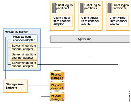
To enable NPIV on the managed system, you must create a Virtual I/O Server logical partition (version 2.1, or later) that provides virtual resources to client logical partitions. You assign the physical fibre channel adapters (that support NPIV) to the Virtual I/O Server logical partition. Then, you connect virtual fibre channel adapters on the client logical partitions to virtual fibre channel adapters on the Virtual I/O Server logical partition. A virtual fibre channel adapter is a virtual adapter that provides client logical partitions with a fibre channel connection to a storage area network through the Virtual I/O Server logical partition. The Virtual I/O Server logical partition provides the connection between the virtual fibre channel adapters on the Virtual I/O Server logical partition and the physical fibre channel adapters on the managed system.
The following figure shows a managed system configured to use NPIV:
on VIO server:
root@vios1: / # lsdev -Cc adapter
fcs0 Available 01-00 8Gb PCI Express Dual Port FC Adapter (df1000f114108a03)
fcs1 Available 01-01 8Gb PCI Express Dual Port FC Adapter (df1000f114108a03)
vfchost0 Available Virtual FC Server Adapter
vfchost1 Available Virtual FC Server Adapter
vfchost2 Available Virtual FC Server Adapter
vfchost3 Available Virtual FC Server Adapter
vfchost4 Available Virtual FC Server Adapter
on VIO client:
root@aix21: /root # lsdev -Cc adapter
fcs0 Available C6-T1 Virtual Fibre Channel Client Adapter
fcs1 Available C7-T1 Virtual Fibre Channel Client Adapter
Two unique WWPNs (world-wide port names) starting with the letter "c" are generated by the HMC for the VFC client adapter. The pair is critical and both must be zoned if Live Partition Migration is planned to be used. The virtual I/O client partition uses one WWPN to log into the SAN at any given time. The other WWPN is used when the client logical partition is moved to another managed system using PowerVM Live Partition Mobility.
lscfg -vpl fcsX will show only the first WWPN
fcstat fcsX will show only the active WWPN
Both of them are showing only 1 WWPN but fcstat will show always the active WWPN which is in use (which will change after an LPM), however lscfg will show as a static value the 1st WWPN assigned to the HBA only.
One VFC client adapter per physical port per client partition and maximum 64 active VFC client adapter per physical port. There is always one-to-one relationship between the virtual Fibre Channel client adapter and the virtual Fibre Channel server adapter.
The difference between traditional redundancy with SCSI adapters and the NPIV technology using virtual Fibre Channel adapters is that the redundancy occurs on the client, because only the client recognizes the disk. The Virtual I/O Server is essentially just a pass-through managing the data transfer through the POWER hypervisor. When using Live Partition Mobility storage moves to the target server without requiring a reassignment (opposite with virtual scsi), because the virtual Fibre Channels have their own WWPNs that move with the client partitions on the target server.
After creating an FC client adapter, and trying to make it persistent across restarts, another different pair of virtual WWPNs would be generated, when creating the adapter in the profile. To prevent this undesired situation, which would require another SAN zoning and storage configuration, make sure to save any virtual Fibre Channel client adapter DLPAR changes into a new partition profile by selecting: Configuration -> Save Current Configuration and change the default partition profile to the new profile.
-----------------------------------------------------
NPIV clients num_cmd_elem attribute should not exceed the VIOS adapter’s num_cmd_elems.
If you increase num_cmd_elems on the virtual FC (vFC) adapter, then you should also increase the setting on the real FC adapter.
-----------------------------------------------------
Check NPIV adapter mapping on client:
root@bb_lpar: / # echo "vfcs" | kdb <--vfcs is a kdb subcommand
...
NAME ADDRESS STATE HOST HOST_ADAP OPENED NUM_ACTIVE
fcs0 0xF1000A000033A000 0x0008 aix-vios1 vfchost8 0x01 0x0000 <--shows which vfchost is used on vio server for this client
fcs1 0xF1000A0000338000 0x0008 aix-vios2 vfchost6 0x01 0x0000
-----------------------------------------------------
NPIV creation and how they are related together:
FCS0: Physical FC Adapter installed on the VIOS
VFCHOST0: Virtual FC (Server) Adapter on VIOS
FCS0 (on client): Virtual FC adapter on VIO client
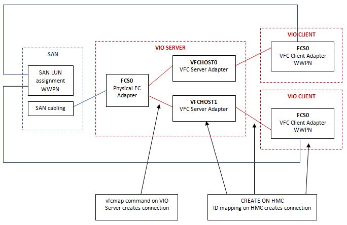
Creating NPIV adapters:
0. install physical FC Adapters to VIO Servrs
1. HMC -> VIO Server -> DLPAR -> Virtual Adapter (don't forget profile (save current))
2. HMC -> VIO Client -> DLPAR -> Virtual Adapter (the ids should be mapped, don't forget profile)
3. cfgdev (VIO server), cfgmgr (client) <--it will bring up the new adapter vfchostX on vio server, fcsX on client
4. check status:
lsdev -dev vfchost* <--lists virtual FC server adapters
lsmap -vadapter vfchost0 -npiv <--gives more detail about the specified virtual FC server adapter
lsdev -dev fcs* <--lists physical FC server adapters
lsnports <--checks NPIV readiness (fabric=1 means npiv ready)
5. vfcmap -vadapter vfchost0 -fcp fcs0 <--mapping the virtual FC adapter to the VIO's physical FC
6. lsmap -all -npiv <--checks the maping
7. HMC -> VIO Client -> get the WWN of the adapter <--if no LPM will be used only the first WWN is needed
8. SAN zoning
-----------------------------------------------------
Checking if VIOS FC Adapter supports NPIV:
On VIOS as padmin:
$ lsnports
name physloc fabric tports aports swwpns awwpns
fcs0 U78C0.001.DAJX633-P2-C2-T1 1 64 64 2048 2032
fcs1 U78C0.001.DAJX633-P2-C2-T2 1 64 64 2048 2032
fcs2 U78C0.001.DAJX634-P2-C2-T1 1 64 64 2048 2032
fcs3 U78C0.001.DAJX634-P2-C2-T2 1 64 64 2048 2032
value in column fabric:
1 - adapter and the SAN switch is NPIV ready
2 - adapter or SAN switch is not NPIV ready and SAN switch configuration should be checked
-----------------------------------------------------
Getting WWPNs from HMC CLI:
lshwres -r virtualio --rsubtype fc --level lpar -m <Man. Sys.> -F lpar_name,wwpns --header --filter lpar_names=<lpar name>
lpar_name,wwpns
bb_lpar,"c05076066e590016,c05076066e590017"
bb_lpar,"c05076066e590014,c05076066e590015"
bb_lpar,"c05076066e590012,c05076066e590013"
bb_lpar,"c05076066e590010,c05076066e590011"
-----------------------------------------------------
Replacement of a physical FC adapter with NPIV
1. identify the adapter
$ lsdev -dev fcs4 -child
name status description
fcnet4 Defined Fibre Channel Network Protocol Device
fscsi4 Available FC SCSI I/O Controller Protocol Device
2. unconfigure the mappings
$ rmdev -dev vfchost0 -ucfg
vfchost0 Defined
3. FC adapters and their child devices must be unconfigured or deleted
$ rmdev -dev fcs4 -recursive -ucfg
fscsi4 Defined
fcnet4 Defined
fcs4 Defined
4. diagmenu
DIAGNOSTIC OPERATING INSTRUCTIONS -> Task Selection -> Hot Plug Task -> PCI Hot Plug Manager -> Replace/Remove a PCI Hot Plug Adapter.
-----------------------------------------------------
Changing WWPN number:
There are 2 methods: changing dynamically (chhwres) or changing in the profile (chsyscfg). Both of them are similar and both of them done in HMC CLI.
I. Changing dynamically:
1. get current adapter config:
# lshwres -r virtualio --rsubtype fc -m <man. sys.> --level lpar | grep <LPAR name>
lpar_name=aix_lpar_01,lpar_id=14,slot_num=8,adapter_type=client,state=1,is_required=0,remote_lpar_id=1,remote_lpar_name=aix_vios1,remote_slot_num=123,"wwpns=c0507603a42102d8,c0507603a42102d9"
2. remove adapter from client LPAR: rmdev -Rdl fcsX (if needed unmanage device prior from storage driver)
3. remove adapter dynamically from HMC (it can be done in GUI)
4. create new adapter with new WWPNS dynamically:
# chhwres -r virtualio -m -o a -p aix_lpar_01 --rsubtype fc -a "adapter_type=client,remote_lpar_name=aix_vios1,remote_slot_num=123,\"wwpns=c0507603a42102de,c0507603a42102df\"" -s 8
5. cfgmgr on client LPAR will bring up adapter with new WWPNs.
6. save actual config to profile (so next profile activation wil not bring back old WWPNs)
(vfc mapping removal did not needed in this case, if there are some problems try reconfig. that one as well at VIOS side)
-----------------------------------------------------
II. changing in the profile:
same as above just some commands are different:
get current config:
# lssyscfg -r prof -m <man. sys.> --filter lpar_names=aix_vios1
aix_lpar01: default:"""6/client/1/aix_vios1/5/c0507604ac560004,c0507604ac560005/1"",""7/client/1/aix_vios1/4/c0507604ac560018,c0507604ac560019/1"",""8/client2/aix_vios2/5/c0507604ac56001a,c0507604ac56001b/1"",""9/client/2/aix_vios2/4/c0507604ac56001c,c0507604ac56001d/1"""
create new adapters in the profile:
chsyscfg -m <man. sys.> -r prof -i 'name=default,lpar_id=5,"virtual_fc_adapters+=""7/client/1/aix-vios1/4/c0507604ac560006,c0507604ac560007/1"""'
-m - managed system
-r prof - profile will be changed
-i ' - attributes
name=default - name of the profile, which will be changed
lpar_id=5 - id of the client LPAR
7 - adapter id on client (slot id)
client - adapter type
1 - remote PLAR id (VIOS server LPAR id)
aix_vios1 - remote LPAR name (VIOS server name)
4 - remote slote number (adapter id on VIOS server)
WWPN - both WWPN numbers (separated with , )
1 - required or desired (1- required, 0- desired)
Here VFC unmapping was needed:
vfcmap -vadapter vfchost4 -fcp <--remove mapping
vfcmap -vadapter vfchost4 -fcp fcs2 <--create new mapping
-----------------------------------------------------
Virtual FC login to SAN:
When new LPAR with VFC has been created, before to see LUNs (to install AIX), for the first time VFC Adapter has to be logged in to SAN.
This can be done on HMC (above HMC V7 R7.3) with command chnportlogin
chnportlogin: it allows to allocate, log in and zone WWPNs before the client partition is activated.
On HMC:
1. lsnportlogin -m <man. sys> --filter lpar_ids=4 <-- list status of VFC adapters (lpar_id should be given)
lpar_name=bb_lpar,lpar_id=4,profile_name=default,slot_num=2,wwpn=c0507607d1150008,wwpn_status=0,logged_in=none,wwpn_status_reason=null
lpar_name=bb_lpar,lpar_id=4,profile_name=default,slot_num=2,wwpn=c0507607d1150009,wwpn_status=0,logged_in=none,wwpn_status_reason=null
lpar_name=bb_lpar,lpar_id=4,profile_name=default,slot_num=3,wwpn=c0507607d115000a,wwpn_status=0,logged_in=none,wwpn_status_reason=null
lpar_name=bb_lpar,lpar_id=4,profile_name=default,slot_num=3,wwpn=c0507607d115000b,wwpn_status=0,logged_in=none,wwpn_status_reason=null
The WWPN status. Possible values are:
0 - WWPN is not activated
1 - WWPN is activated
2 - WWPN status is unknown
2. chnportlogin -m <man. sys> --id 4 -o login <-- activate WWPNs (VFC logs in to SAN)
3. lsnportlogin -m <man. sys> --filter lpar_ids=4 <-- list status (it should be wwpn_status=1)
lpar_name=bb_lpar,lpar_id=4,profile_name=default,slot_num=2,wwpn=c0507607d1150008,wwpn_status=1,logged_in=vios,wwpn_status_reason=null
lpar_name=bb_lpar,lpar_id=4,profile_name=default,slot_num=2,wwpn=c0507607d1150009,wwpn_status=1,logged_in=vios,wwpn_status_reason=null
lpar_name=bb_lpar,lpar_id=4,profile_name=default,slot_num=3,wwpn=c0507607d115000a,wwpn_status=1,logged_in=vios,wwpn_status_reason=null
lpar_name=bb_lpar,lpar_id=4,profile_name=default,slot_num=3,wwpn=c0507607d115000b,wwpn_status=1,logged_in=vios,wwpn_status_reason=null
4. Storage team can do LUN assginment, after they finished, you can do logout:
chnportlogin -m <man. sys> --id 4 -o logout
-----------------------------------------------------
IOINFO
If HMC is below V7 R7.3 ioinfo can be used to cause VFC adapters to login to SAN.
ioinfo also can be used for debug purposes or to check if disk are available/which disk is boot disk
It can be reached from SMS menu with number: 8 (Open Firmware Prompt)
IBM IBM IBM IBM IBM IBM IBM IBM IBM IBM IBM IBM IBM IBM IBM IBM IBM IBM IBM
IBM IBM IBM IBM IBM IBM IBM IBM IBM IBM IBM IBM IBM IBM IBM IBM IBM IBM IBM
IBM IBM IBM IBM IBM IBM IBM IBM IBM IBM IBM IBM IBM IBM IBM IBM IBM IBM IBM
1 = SMS Menu 5 = Default Boot List
8 = Open Firmware Prompt 6 = Stored Boot List
Memory Keyboard Network SCSI Speaker ok
0 > ioinfo
!!! IOINFO: FOR IBM INTERNAL USE ONLY !!!
This tool gives you information about SCSI,IDE,SATA,SAS,and USB devices attached to the system
Select a tool from the following
1. SCSIINFO
2. IDEINFO
3. SATAINFO
4. SASINFO
5. USBINFO
6. FCINFO
7. VSCSIINFO
q - quit/exit
==> 6
Then choose VFC client device from list --> List Attached FC Devices (this will cause that VFC device to login to SAN)
After that on VIOS: lsmap -npiv ... will show LOGGED_IN
(to quit from "ioinfo" command "reset-all" will do a reboot of the LPAR)
-----------------------------------------------------
| VSCSI (0) | 2016.07.18 |
|---|---|
| SEA (0) | 2016.07.18 |
| VIO 가상 아답터 생성 (0) | 2016.07.18 |
| VIOS OS mirror (0) | 2016.07.18 |
| SR-IOV - vNIC (0) | 2016.07.18 |
| SEA (0) | 2016.07.18 |
|---|---|
| NPIV (0) | 2016.07.18 |
| VIOS OS mirror (0) | 2016.07.18 |
| SR-IOV - vNIC (0) | 2016.07.18 |
| Shared Storage Pools (SSP 구성) (0) | 2016.07.18 |
$ extendvg –f rootvg hdisk1
$ mirrorios hdisk1
| SEA (0) | 2016.07.18 |
|---|---|
| NPIV (0) | 2016.07.18 |
| VIO 가상 아답터 생성 (0) | 2016.07.18 |
| SR-IOV - vNIC (0) | 2016.07.18 |
| Shared Storage Pools (SSP 구성) (0) | 2016.07.18 |